POLANO Polarized Illumination
Steppers have continually shrunk the feature size of printed wafers as projection lens N.A. has increased and light source wavelength has shortened. However, as such developments approach their theoretical limit, we can no longer expect great progress using conventional technologies alone. In 2003, Nikon introduced immersion lithography technology, enabling super-resolution without drastic changes to any process. The revolutionary technology of POLANO*1 also increases contrast and realizes resolution that is a half-generation ahead.
"Polarization" refers to the direction of vibration of the electric field in a light wave. Natural and many artificial light sources, including the current generation of lithography tools, emit "unpolarized light," meaning that the light consists of many different rays with randomly oriented polarization. On the other hand, "polarized light" is light whose electric field vibrates in a single direction. POLANO lighting technology ingeniously controls this polarization, the direction of light’s vibration in electric fields, in order to increase contrast of the projected image.

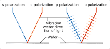
Fig. 1
Fig. 1 shows polarization conditions of two kinds of polarized light. In s-polarization, the vibration direction is parallel to the wafer. In p-polarization, the vibration vector direction is parallel to the blue plane shown in Fig. 2.
Fig. 2
This is important because the projection lens constructs its images by making two light beams interfere with each other. Light beams coming through the projection lens create bright and dark patterns on the resist on the wafer by interference. Light is a wave with peaks and troughs. Two peaks join to raise the resulting peak, and two troughs join to deepen the resulting trough. This is called interference and the size of the peaks and troughs is called amplitude.
In p-polarization, the two rays have polarization vectors that meet at a different angle, so the amplitude cannot be simply added. Effectively, some of the light amplitude is wasted. Fig. 2 shows that horizontal elements are the same as each other, but vertical elements are opposed to each other, so the vertical elements tend to cancel each other out, but the horizontal elements don’t contribute. Lower contrast is the result.
In s-polarization, the two rays have polarization vectors that meet directly parallel to each other, effectively using the full strength of the light. The amplitudes of the waves are simply added, and strength of the light can be derived by squaring the amplitude. Contrast is maximized.
As shown in the graphs indicating the strength of lights in Fig. 2, higher contrast can be obtained with s-polarization. Therefore, s-polarization is more suitable than p-polarization for exposing detailed circuit patterns. P-polarization would be worse, and unpolarized light is a combination of both, so it is in the middle.
Up until now, unpolarized light has been used in steppers. The light source used in the latest stepper is an ArF excimer laser*2 with 193nm*3 wavelength, and this light actually is already polarized in one direction. To cancel the polarization effect, this light is used after depolarization. This is because there was no technology to control and measure the polarization, and the condition of polarization was not uniform among different steppers.
With higher N.A., the effect of p-polarization in unpolarized light can no longer be ignored. The higher the N.A., the more shallow are incident angles of the two beams, and the larger the p-polarization effect, which degrades contrast. With s-polarization, higher N.A. has no negative effect.
With POLANO, all the light beams are polarized in the right direction. This is because polarization control technology derived from a newly developed phase plate does not degrade illumination. A measuring unit for the condition of polarization on wafer surfaces was also developed for POLANO. Measurement results are analyzed and used for fine-tuning phase board direction in order to obtain optimal uniform polarized illumination for any steppers.

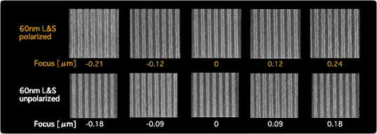
Fig. 3
When POLANO is applied to the NSR-S308F ArF excimer laser stepper (N.A. 0.92), which has resolution of 65nm or lower, image contrast improves by 20% and realizes resolution of 60nm, which is a half-generation ahead of the current technology.
Also, improvement of image contrast not only improves resolution, it helps realize a "uniform circuit pattern" in IC production lines. With high contrast, change in the line width is minimized, even when illumination output energy varies, which typically leads to error, or exposure is uneven on a wafer. In other words, production increases without affecting the conventional production process since defective products decrease.
POLANO, along with immersion lithography steppers with N.A. above 1, is expected to produce excellent results in the near future. Without drastically changing conventional exposure processes, POLANO enables the production of next-generation IC that is leading to new developments in optical technology.
- *1Polarization optimization for lithographic advance in NSR optics.
- *2With a wavelength of 193nm, this type of laser is named after the inert gases used for discharge excitation: a mixture of argon (Ar) and fluorine (F) halogen.
- *3One billionth of a meter (10-9 meters).
