Evanescent Light
Evanescent is defined as "temporal" or "fleeting". Unlike normal light, evanescent light is extremely limited in terms of the distance it can be propagated. There are a number of structures in which evanescent light is generated, but the most common generating mechanism is that shown in Fig. 1.
Fig.1
If the incident beam hits surface A, the light is refracted and escapes through surface B. However, if the incidence angle becomes larger than a fixed number, all of the light is reflected off of surface B and escapes through surface C. At this time, evanescent light permeates surface B (the purple area in Fig. 1). As its thickness is less than a single wavelength of light, an extremely thin layer of evanescent light (1μm* or less) is generated. This light is not propagated from the prism, thus it is invisible to the naked eye.
Fig.2
Fig. 2 illustrates a simple method for confirming the existence of evanescent light. Another prism is brought toward the original prism. Should the prisms come together as one, surface B no longer reflects light. The light instead escapes through surface D.
Light begins escaping through surface D even before the space between the two prisms disappears. This is where evanescent light comes in. If there is no evanescent light present at surface B, unless light reflected off of surface B escapes the prism, nothing should happen until the prisms come completely together — no matter how close they may be.
If another prism is brought close to the original prism immediately before the evanescent light clinging to surface B begins to dissipate, it recovers and is transformed into normal propagating light which permeates the upper prism (Fig. 2). At this point, surface B is no longer 100% reflective. Its reflectivity weakens in proportion to the power of the light which has escaped into the upper prism.
Evanescent light is not propagated in the same manner as normal light. It takes the form of a layer of mist which clings to the surface of an object. However, if small particles are present in the area where the evanescent light is generated, the light will be dispersed and refracted, causing a portion of it to be converted into normal light.
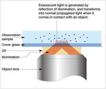
Fig.3
One example of Nikon having applied the characteristics of evanescent light — specifically its thinness and its ability to be transformed into normal light — is the Evanescent Wave Imaging System. Its basic structure and principles are illustrated in Fig. 3.
From the perimeter of the oil immersion-type objective lens, a very wide-angle incidence of light is emitted into the oil, then incidence occurs on the cover glass. On the upper surface of the glass is a specimen in a thin layer of water. Since the refractive index of glass (1.5) is higher than that of water (1.33), the light is reflected off the undersurface of the cover glass. At the same time, a very thin layer of evanescent light is generated on the upper surface, illuminating a very small portion of the specimen being observed. The evanescent light interacts with objects (indicated by red dots) within the specimen, causing the light to transform into normal propagating light and making the aforementioned objects visible through the microscope. Though the forms of interaction between the evanescent light and objects in the specimen include dispersion, diffraction and absorption of light with subsequent emission of fluorescence, the evanescent microscope imaging system is used primarily for observing fluorescence.
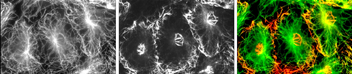
This sample is a fiber bud cell (3T3 cell) taken from the skin of a mouse, observed using reflective fluorescent illumination and evanescent light. In the picture to the left (reflective fluorescent illumination), microtubules can be seen throughout each cell. In the center picture (evanescent light), however, microtubules are only visible around the circumference and at the nucleus of each cell. Since only microtubules near the cover glass are being observed, there is no interference from the light of other layers, and a high-sensitivity, high-contrast image can be obtained. The picture to the right is a Superimposition of the other two pictures. This illustrates that it is possible to discern the three-dimensional structure of a cell.
The biggest advantages in the application of evanescent light to microscopes are the elimination of blurred images, and the ability to observe very low light such as the fluorescence of a single molecule within the focus area with no background light interference. Evanescent light forms in a very thin layer, which means it illuminates only a very shallow area — a key benefit in this particular application. If the area illuminated is too deep, in addition to the primary object which is clearly seen, other objects which are not as clear will also come into view. In other words, the evanescent microscope imaging system uses the natural characteristics of evanescent light to effectively define and restrict the field of view.
There are ways other than reflection by which evanescent light can be generated. One such method is diffraction — light generated in this manner enables images to be obtained which are of higher resolution than those captured by the standard optical imaging system.
Fig.4
Fig. 4 provides a simple, theoretical demonstration of diffraction, using a diffraction grating. In the figure we can see numerous rays of light being directed via a diffraction grating. At this point, the light with the largest diffraction angle would have the most detailed object information. In order to capture the diffraction grating image as faithfully as possible, the largest available lens should be used to catch the light with a very large diffraction angle. Lenses do have their limits, however, and even the biggest lens can only catch the light that is propagated in the air.
In this hypothetical situation, when a great amount of light passes through the diffraction grating, evanescent light is generated, and clings to the outer surface of the grating. This light contains a surprising amount of useful, detailed information.
The lens is removed and the wafer is moved as closely as possible to the undersurface of the diffraction grating to catch the evanescent light. Naturally the diffracted light is captured as well. The evanescent light acquires even more detailed information, which causes a dramatic increase in resolution. The resulting image from the diffraction is of considerably higher resolution than was possible with standard optical imaging systems. It almost seems obvious, since the wafer onto which an image has been projected can be moved as closely as possible to the diffraction grating, but explaining the process using the diffraction phenomenon clearly shows the potential of evanescent light.
This experiment demonstrates evanescent light’s superiority to normal light in terms of dispersion, enabling the light to retain the information required for maximum lateral resolution. The previous example involving the microscope showed the benefits of its generation in layer form, which greatly enhances vertical resolution.
Evanescent light devises its own methods of generation, and a variety of applications can be considered by taking advantage of this characteristic. In addition to the concepts introduced here, more developments are anticipated based on the unexpected behavior of light and electrons in the presence of evanescent light. It is a dream holding much promise and countless undiscovered possibilities.
- *One millionth of a meter.
Posted July 2004