Nikon Measuring Instruments User Case Study — 6 — Nikon Corporation Instruments Company
In this 6th installment in a series on manufacturing sites that use Nikon measuring instruments to manage product quality, we visit NIKON CORPORATION Instruments Company, Japan for
a feature on Nikon autocollimators.
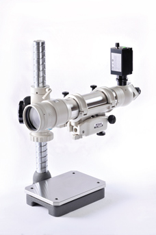 The latest model—the Autocollimator 6B with LED light source
An autocollimator is an optical device for making angular measurements. It measures microscopic angular differences or deviations to check various properties such as straightness, parallelism, and deflection. It is an important tool necessary for checking precision in the manufacture of optical instruments and machine tools.
The Autocollimator 6B is a long-selling product that was launched in 1963. A sister device, the Autocollimator 6D, was launched in 1964 and has been on sale ever since.
The following description includes comments by Takahiko Matsumoto, who was formerly one of the people responsible for both these products.
The principle of the autocollimator
 Takahiko Matsumoto: Industrial Instruments Development Department, Nikon Instruments Company. Mr. Matsumoto was in charge of autocollimators for approximately 15 years.
An autocollimator is a device that generates parallel beams of light and then measures them.
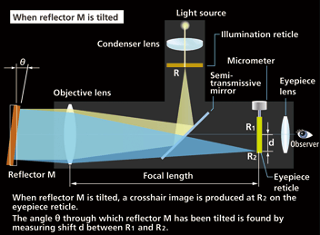
Mr. Matsumoto explains how an autocollimator works. “Light from the light source passes through crosshair R in the illumination reticle and is bent through a right angle by the semi-transmissive mirror. This light passes through the objective lens and becomes parallel beams. It is then directed towards reflector M, is reflected back through the objective lens, and finally produces crosshair image R1 on the eyepiece reticle. This is known as ‘autocollimation.’
“If reflector M is tilted by an angle of ø, crosshair image R2 is produced on the eyepiece reticle. Measuring the shift d between R1 and R2 enables the angle ø, the angle of tilt for reflector M, to be calculated. The observer reads off the value from the scale on the eyepiece micrometer, which enables high-precision measurement to an accuracy of 0.5 seconds of arc.”
- * 0.5 seconds of arc = 1/7200 of 1 degree
The autocollimator—vital to precise
angular measurement
The autocollimator is used in various industrial fields. For example, machine tool manufacturers use the method shown in Figure 1 to measure the straightness of guide surfaces in the course of the manufacturing process. Guide surfaces have an important role in regulating the rectilinear motion of machine tools. The straightness of a guide surface can be found based on the values obtained by placing a stand with a reflector on the guide surface and successively moving the stand by a fixed distance and reading off the angle in each position.

Figure 1 Measuring a guide surface
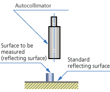
Figure 2 Measuring parallelism
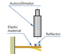
Figure 3 Measuring elastic material
Figure 2 illustrates the method for measuring the degree of parallelism between two flat surfaces. Two crosshair images—one from the reflecting surface to be measured and the other from the standard reflecting surface—are visible at the same time, and the difference between them is read off on the autocollimator. Alternately blocking the optical path from the surface to be measured and the standard reflecting surface makes it possible to determine which surface the crosshair image is originating from.
Figure 3 illustrates the method for measuring the deflection in an elastic component by mounting a reflector on it. Conversely, the application for this could be the estimation of external force based on the level of deflection.
Nikon uses both the Autocollimator 6B and Autocollimator 6D for various in-house checks. In the photograph, an Autocollimator 6B is being used to check the stand of a ShuttlePix digital microscope. While the stand is moved up and down, the straightness is measured to check that it meets precision standards.
Measuring the radius of curvature for convex and concave surfaces
Mr. Matsumoto explains the strengths of the Autocollimator 6B and 6D. “The light rays can be made to diverge or converge by turning the objective correction ring. This function allows measurement of the radius of curvature for convex and concave surfaces. As shown in Figure 4, the autocollimator is placed so that it is facing the convex or concave surface and the observer turns the objective correction ring so that the crosshair image produced by the reflection is clearly visible. The radius of curvature for the convex or concave surface can now be read off the scale on the objective correction ring.”
Fundamental to the working of the autocollimator is the assumption that the emitted light and the incident light will be parallel to each other. If the reflector is not flat enough, however, the incident light will not flow parallel. The purpose of the autocollimator′s objective correction ring is to allow the user to correct for this. The ring also has this secondary use, in that it permits the observer to measure the radius of curvature of a convex or concave surface.
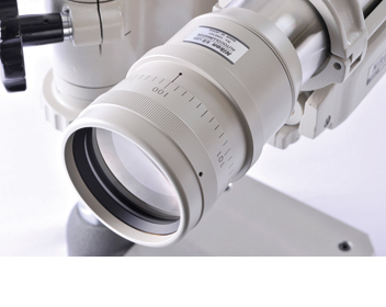
Objective correction ring
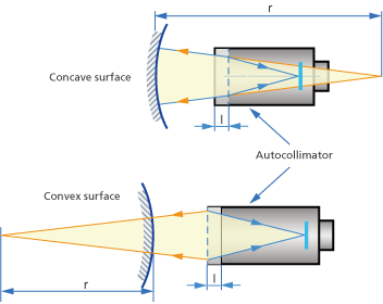
Figure 4 Measuring the radius of curvature
The radius of curvature (r) is measured by the amount of movement of the objective correction ring (l).
The dark viewfield Autocollimator 6D—sister machine to the Autocollimator 6B
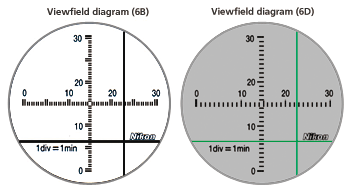 Viewfield diagram (6B) and viewfield diagram (6D)
On the Autocollimator 6B there is a crosshair pattern on the illumination reticle, whereas on the Autocollimator 6D there is a crosshair-shaped slit in the illumination reticle. In other words, the Autocollimator 6B is a bright viewfield instrument in which a black crosshair image is visible on a bright viewfield, while the Autocollimator 6D is a dark viewfield instrument in which a bright crosshair image is visible on a dark viewfield.
If the object is small and there is little reflected light because only a small reflector can be installed, it will be difficult to read the scale on a brightfield instrument, since the entire viewfield will be dark. As a result, it is easier to use a darkfield instrument in such instances.
The first Nikon autocollimator—built in 1942
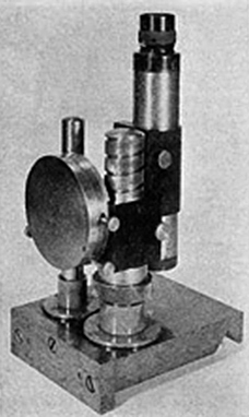 Autocollimator accurate to 1 minute of arc (1942)
In 1942, Nikon (then known as Nippon Kogaku K.K.) completed work on an autocollimator that gave readings accurate to one minute of arc. The company then built a model giving readings accurate to 5 seconds of arc in 1943, followed by a model with readings accurate to 10 seconds of arc in 1944. A light bulb was used as the light source on the model accurate to 5 seconds of arc (the other devices used a method involving a light window).
This model also boasted a structure that was already similar to the autocollimators of today, with a semi-transmissive reflector installed between the objective lens and the eyepiece lens, and the optical path split into two.
Lack of design change shows user confidence
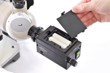 The switch to an LED light source allowed the device to run off two AA batteries. This made the device easier to use and it can still be operated for long periods—even without mains power.
The Autocollimator 6B and Autocollimator 6D boasted a higher level of read-out accuracy of 0.5 seconds of arc compared to their predecessor, the Autocollimator 5, which was accurate to 1 second of arc.
Although eco-glass was subsequently adopted, the external coating was changed, and the light bulb was replaced by an LED as the light source, the basic design remains unchanged.
“There has been almost no reason or need to change the design. Ordinarily, making changes or improvements to a product increases customer satisfaction. However, this is not the case with these two models.”
When the light source was changed to an LED, an attempt was made to increase the visibility of the crosshair image by making the color more saturated than that of light bulbs, which had been used previously. However, it is said that veteran users within the company monitoring the prototype pointed out that if the appearance differed from what the user was accustomed to, this could hinder measurement work using autocollimators.
Hence, the design was altered so that the appearance differed little from that of previous models.
“For the developers, it was slightly disappointing not be able to make modifications. However, we understood that the device was so close to perfect that customers loved it.”
Boasting ample functionality, precision, and operability at its very launch, the model was in virtually no need of improvement.
Since it had become established as a standard device at various production sites, ill-considered changes would not have been tolerated. This helped to make the Autocollimator 6B and 6D such long-selling products.
The favored models of skilled technicians, the Autocollimator 6B and 6D are still providing excellent service in many workplaces today. This continuity is evidence of user confidence in the product.
This article is a re-edited version of “Recollections—Long-selling products, historical products and technologies: Autocollimator 6B”.
