
The ruling engine is a machine tool used for manufacturing diffraction gratings. Until the 1960s, it was known in Japan as the "fantasy machine" since the ultra-high precision required for its manufacture was extremely difficult to achieve. The first ruling engine made in Japan (hereafter Ruling Engine No. 1) was manufactured by Nikon (formerly Nippon Kogaku K.K.). This is the story of Ruling Engine No. 1 with comments by Shoichiro Yoshida*1, who was in charge of its development.
- *1Shoichiro Yoshida:
Joined Nikon (formerly Nippon Kogaku K.K.) in 1956. After working on development of astronomical telescopes and ruling engines, he developed IC steppers and scanners. He became president in 1997, Chairman & CEO in 2001, and from 2011 a senior counselor for Nikon.
Ruling engines and diffraction gratings
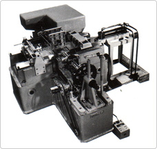
Ruling Engine No. 1
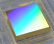
Diffraction grating (not manufactured using Ruling Engine No. 1)
A diffraction grating is a key part of a spectroscope, which consists of a glass plate or mirrored surface with fine grooves set into it, and which uses diffraction and interference of the light passing through it or reflected on it to produce a spectrum. Spectroscopes are used in a variety of ways, one of which is astronomical observation, in which they are used to analyze the light from celestial objects.
The diffraction grating produced in 1881 by Professor Rowland*2 of Johns Hopkins University*3 (who was known as the "father of the diffraction grating") consisted of a glass surface engraved with 660 grooves per millimeter.
Although this kind of precision work had been carried out in the West for a long time, it was not until the 1960s that it became possible to manufacture diffraction gratings in Japan. In those days, Japan imported diffraction gratings but there were procurement problems, such as models with requisite specifications, since they were imported and expensive.
A normal diffraction grating contains approximately 1,000 grooves per millimeter. In other words, the interval between the rulings is less than 1 micrometer. In addition, the grooves must be inscribed in parallel with one another and with equal intervals between them. The production of such fine rulings requires a "ruling engine."
- *2University in Maryland, USA, founded in 1876
- *3 Professor Henry Augustus Rowland—American physicist from the latter half of the 19th century.
The fantasy machine
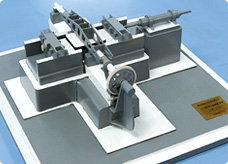
Wooden 5:1 scale model of Ruling Engine No. 1, made by the Tokyo Institute of Technology's Precision and Intelligence Laboratory, at Nikon's Kumagaya plant. The whereabouts of the device itself is unknown and it is highly likely that it no longer exists.
The Japanese had wanted to manufacture ruling engines and begin domestic production of diffraction gratings. In 1916, a prototype ruling engine had been constructed in an effort led by Dr. Hantaro Nagaoka of the Institute of Physical and Chemical Research (RIKEN). However, it never became a commercial reality and this led to the moniker "fantasy machine."
It was in 1961 that the Ministry of Education, Science and Culture (now known as the Ministry of Education, Culture, Sports, Science and Technology) began a ruling engine development project once again. The project was overseen by the Optical Research Institute of the Tokyo University of Education (the present-day University of Tsukuba). With the selection of Masao Nagaoka, the president of Nippon Kogaku K.K. (now Nikon), as a member of the project's consultative committee, along with representatives from organizations that included the Central Inspection Institute of Weights and Measures (the present-day National Institute of Advanced Industrial Science and Technology—AIST), the Tokyo Astronomical Observatory (the present-day National Astronomical Observatory of Japan—NAOJ), and Osaka University. Nikon took charge of the production of the Ruling Engine No. 1.
In reality, it was Shoichiro Yoshida, who had been in charge of the development of large telescopes in Nikon's Custom Machine Department, who was then in charge of the development of the Ruling Engine No. 1. At the time, he was in his fifth year at Nikon. Remembering when he went to look at the abortive pre-war prototype ruling engine at RIKEN, Mr. Yoshida says:
"The prototype clearly illustrated the difficulties that the engineers had faced. However, it was a very primitive device."
With little to be learned from the prototype, the project was essentially starting from scratch. The time span for the project was a mere three years, with the entire first year being devoted to completing the specifications and blueprints.
Original ruling method
Method used by ruling engines in the West
Method used by Ruling Engine No. 1
The basic concept of the Ruling Engine No. 1 is based on the results of four years of pure research by the Tokyo Institute of Technology's Precision and Intelligence Laboratory that began in 1956 on a diffraction grating ruling machine for the Ministry of Education, Science, Sports and Culture.
A ruling engine uses a diamond cutter to shave grooves into a glass surface that has been coated with a metal, such as aluminum, by means of vapor deposition. For 1,000 grooves to be shaved into 1 millimeter, the pitch (interval between the grooves) must be 1 micrometer. Advanced control technology is required in order to grind in a dead straight line while reliably maintaining such a fine pitch.
The ruling method usually adopted in ruling engines constructed in the West was to set the pitch by moving the glass plate intermittently and move the diamond cutter in a reciprocating motion (back and forth).
The ruling method employed in the Ruling Engine No. 1 using the basic concept, however, involved setting the pitch by moving the diamond cutter intermittently and moving the glass plate in a reciprocating motion.
Mr. Yoshida speculates that the rationale in devising this method was as follows: "Lightening the tool stage on which the diamond cutter is mounted enables more precise control of the tool stage than controlling the work stage on which the glass plate is mounted. It was probably thought that with the tip of the diamond cutter and the lead screw that moves the tool stage configured for collinear movement, a higher degree of precision could be achieved. In other words, it can be assumed that the Abbe Principle*4 was taken into consideration when making precision machinery. "
- *4A principle that states that if the calibration marks on a standard rule (such as a measuring machine) and the object being measured are arranged in a collinear fashion, any measurement error will be small. It is believed that the collinear configuration of the tip of the diamond cutter and the lead screw in Ruling Engine No. 1 was intended to reduce measurement errors.
Overcoming the difficulties and completing the task
The design and manufacture of each component were allotted to the different universities and research institutions participating in the project. However, there were often times when even the top-line components manufactured by experts did not go together smoothly.
Mr. Yoshida describes the stresses of the time as follows: "It felt as if, despite the fact that we had got the parts exactly right, something was lacking in the machine's overall design."
Contemporary documents state that "Nippon Kogaku K.K. has manufactured the mechanical parts and optical devices for the ruling machine, and to carry out overall coordination." Nikon brought to bear the precision work of its skilled technicians on the manufacture of most of the components—principally the optical components, such as the interferometer. Nikon also demonstrated its talent for overall coordination of the finishing and assembly of machines.
In 1964 (the final year of the project), the construction of Ruling Engine No. 1 was completed and it was installed in a special room at the Tokyo University of Education's Optical Research Institute.
Issues with actual operation
The Ruling Engine No. 1 was placed on a fixed foundation that had been firmly embedded in the ground. However, it proved impossible to avoid the effects of the vibrations generated by the machine itself, or by slight earthquakes imperceptible to humans. In those days, it required nine-and-a-half days to produce a diffraction grating 100 mm by 100 mm with approximately 900 grooves ruled per millimeter. Even the slightest earthquake during that period would render the accurate engraving of rulings impossible, and the insufficient rigidity of some of the components caused distortion to occur.
For a variety of reasons, the machine continually failed to achieve the sought-after degree of precision.
Improvements and dreams of a second machine
Although for a while it had appeared to be a success, Ruling Engine No. 1 was never able to attain the level of performance that was necessary for it to be used in practice. When the three years were up, the project team was disbanded. However the desire to begin domestic production of diffraction gratings did not abate. Even after the disbandment of the project team, volunteers continued to make improvements. After finishing his own daily work, Mr. Yoshida would also drop in at the institute and take part in the work on refining the machine.
Eventually the Ruling Engine No. 1 was limited to producing small diffraction gratings for academic research purposes.
Mr. Yoshida still wanted to successfully construct a ruling engine that would be up to actual use and which would be the equal of machines manufactured in the West. Thus, the dream of developing the "fantasy machine" continued and transformed into the quest to build Ruling Engine No. 2.