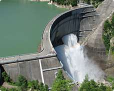
Kurobe Dam
Kurobe Dam is situated in the upper reaches of Kurobe River in the eastern part of Toyama Prefecture. At 186 meters, it is Japan's highest dam. Construction work on the dam began in 1956. The cost amounted to 51.3 billion yen and over 10 million people were involved in the project over the course of seven years. Nikon has also been closely involved with Kurobe Dam—a giant hydro-electric power generation dam that is one of the most prominent of its kind in Japan.
With a total reservoir capacity of 200 million cubic meters (at the time of construction), Kurobe Dam handles enormous water pressure. There is huge variation in this pressure, as the water volume rises and falls with the seasons. Naturally, the dam is changing in shape, and this is also affecting the bedrock that comprises the foundations. To monitor this behavior, a multitude of equipment has been set up and two instruments manufactured by Nikon are still used at Kurobe Dam today.
Coordinate meters installed inside the dam
The body of Kurobe Dam is arch-shaped, and this arch is subjected to enormous water pressure. It is vital to measure the displacement of the arch, and this is carried out using a device known as a "plumb bob" In 1965, Nikon (then named Nippon Kogaku K.K.) manufactured the coordinate meters that are used with this plumb bob.
There is a vertical shaft inside the body of the dam for the plumb bob. A winch is securely fixed to the upper part of the shaft, and a stainless steel line with a heavy plumb bob attached is suspended from the winch. To avoid corrosion and unnecessary vibration, the plumb bob is immersed in an oil tank, and there is a second winch halfway along the stainless steel line to eliminate any bending in it.
The line is vertically stable due to the weight of the plumb bob. However, even if the shape of the body of the dam changes only slightly, the horizontal position of the line will change. It is the coordinate meter that reads this horizontal position and converts it to X, Y coordinates. These values are measured regularly over the long term and are used to monitor the periodical displacement of the body of the dam.
The curvature of an arch dam ensures that the water pressure is distributed to the bedrock of the hillsides on both banks. For this reason, measuring the displacement of the bedrock, as well as that of the arch, is an important task, and this measurement is performed using a "reverse plumb bob"—essentially an inverted plumb bob.
A vertical shaft is bored from the body of the dam to the bedrock, and a stainless steel line is fixed into the bedrock. Meanwhile, in the upper part of the shaft there is a mechanism consisting of a float attached to the line that is suspended in a water tank. Any displacement in the bedrock is reflected by displacement in the line, which is measured by the coordinate meter.
The coordinate meter shown in the photograph is located in a measurement room called P10 on the right bank. Here, the stainless steel line that extends from the bedrock 50 meters below is measured by observing the reverse plumb bob. The line is covered with transparent acrylic so that it will not sway in the wind.
On an ordinary dam a small number of coordinate meters are situated in the middle and on both sides of the body of the dam. On Kurobe Dam, however, there are no less than 22 installed devices, including the plumb bob and the reverse plumb bob. In fact, during the construction of Kurobe Dam , Malpasset Dam in France collapsed with the loss of many lives. It is said that since the two dams have a similar structure and the bedrock around Kurobe Dam site is weak, a precision measurement system was deemed a necessity.
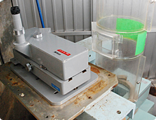
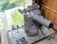
A coordinate meter
The observer looks through the eyepiece on the left, turns the knob to line up the stainless steel line in the crosshairs in the field of view, and reads the displacement measurement scale. Turning the knob on the top of the device switches between the X- and Y-directions.
Telescopes for collimation measurement for observation from both banks
Collimation telescopes set up on the left bank
Measuring the left wing
Effective diameter of the objective lens: 80 mm; magnification: 60x; field of view: 40°; minimum focal distance: 5 m; accessories: special-purpose auxiliary spirit level
The other Nikon product that is used for observing Kurobe Dam is the telescope for collimation measurement, also known as a collimation telescope, which was also installed in 1965. The collimation telescopes are installed in two measurement huts on the right bank and one measurement hut on the left bank. From each measurement hut, a collimation telescope measures the top surface of the body of the dam.
Why are three collimation telescopes used? If Kurobe Dam is seen from above, the central part is in the shape of an arch, while the left and right sides are straight sections that abut the mountains on each bank. It was initially intended that the arch would extend to both banks. However, it was realized that the bedrock of the section in which both ends of the arch were to be secured was weak and would not withstand the water pressure. Consequently, the extreme ends of the arch were substituted by robust linear embankments on both sides.
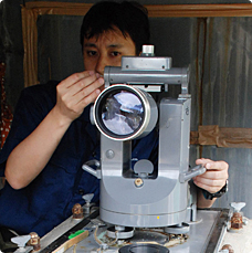
Maintenance work on a collimation telescope
These linear embankments are called "wings." Thus, Kurobe Dam consists of three structures: the right wing, the left wing, and the arch. In order to take accurate measurements of each of these three structures, three collimation telescopes have been set up. It is said that fluctuations in the water pressure have displaced the upper part of the arch by as much as 40 millimeters. Nikon-Trimble Co., Ltd is responsible for the maintenance of the collimation telescopes. Since the telescopes are outdoors, maintenance starts with cleaning. Each telescope is then laid out level using a special purpose spirit level, and finally each part is checked and inspected. Since these are old products, maintenance becomes more difficult every year.
At the time the telescopes were installed, they were advanced optical instruments touted as "Japan's first ever telescope for full-scale dam collimation and very-high-magnification precision measurement." Actually looking through the telescope reveals a high level of magnification and a field of vision so astonishingly clear that it is hard to imagine that it is around 50 years old.
Even after all this time, Nikon products are still used to observe the behavior of Kurobe Dam and to watch over its changes.
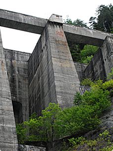
Measurement hut on the right bank
Hut is situated on top of a concrete structure several dozen meters high
Measurement of the amount of displacement of the body of the dam using a collimation telescope
Observer 1 lines up a fixed collimation point from the measurement hut in the crosshairs of the collimation telescope. Observer 1 then lowers the telescope vertically. If there is no displacement of the body of the dam, the adjustable marker lines up with the crosshairs of the collimation telescope. If there is displacement between the collimation point and the adjustable marker, observer 2 reads off the amount of displacement from the scale on the adjustable marker. This refers to the amount of displacement of the body of the dam.
Compiled with the cooperation of NEWJEC Inc.