What is the objective in developing the optical radiation pressure microprobe unit?
Please outline the equipment for us.
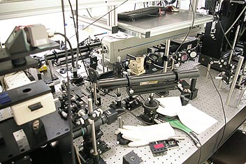
The entire assembly during basic experimentation. As can be seen, it takes up the entire surface of the desk. The long, white box-shaped device is a YAG laser vibrator.
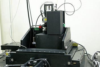
Optical radiation pressure microprobe units mounted on a nano-CMM
The two upper boxes in the center are optical radiation pressure microprobe units manufactured in the course of this project. The entire assembly enables measurement to be carried out at the nm level.
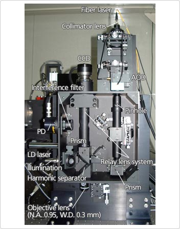
The internal structure of an optical radiation pressure micro-probe unit
From the upper right corner, laser light for optical trapping is radiated and led to the lower left objective lens. The left side is the optical system for detection and observation.
At the basic experimental stage, it consisted of an optical system that focused and controlled the laser and a mechanism for raising the particles that were on the stage. Since the basic experiments required a high-output pulse laser (or YAG laser), as explained previously, the assembly as a whole was huge and covered an entire table.
The current optical radiation pressure microprobe unit is approximately the size of an A4 file. Since the technique of vibrating the stage is used to lift the particles, a 1064-nm-wavelength infrared CW laser (or fiber laser) is employed for the sole purpose of laser trapping. Luckily, a compact fiber laser came out that was of exactly the same wavelength as the pulse laser that we were using in our basic experiments.
The device overall is comprised of three mechanisms: a laser-trapping mechanism, a structure for operating a captured particle as a probe, and a mechanism for observing the action of the probe and detecting its position. Nikon put great effort into reducing the device's footprint from the size of an entire table to A4 size.
As it was assumed that this device would be incorporated into larger mechanisms as a sensor, it needed to be as compact as possible. It was initially envisaged that the finished device would be approximately the same size as a sausage. We thought that it would be good if we could make it about the size of a fish sausage (laughs). As a practical matter, with precision at a premium, a long focus lens system is required; however, that would be difficult at this stage. Although we came up with the basic design here, Nikon put great effort into the design of the optical system, just to get the device down to its current size.
We do possess the research equipment and technology to build a large optical system. However, once you actually try to build the device, implementation requires various skills, such as design ability, mechanical engineering capability, and manufacturing capability. A university lacks this kind of expertise. Nikon, after all, seemed to be the best option. We did sound out other manufacturers; however, since this was a device that no-one had ever built before, we didn't know how it would work until it had been completed. The truth is that only Nikon has a proven track record in the development of this kind of device and fulfills the conditions that I mentioned earlier. Thanks to Nikon, it works perfectly. This is the first device of its size ever built that can trap an object in air.
What is the objective in developing the optical radiation pressure microprobe unit?
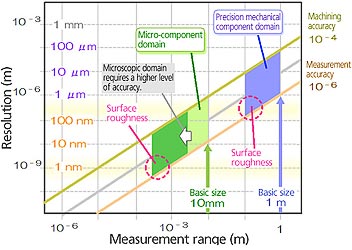
The horizontal axis shows the size of manufacturing components while the vertical axis shows the measurement precision required. For example, components with basic dimensions of 1 m require a processing precision four orders of magnitude higher (at 0.1 mm) and a measurement precision a further two orders of magnitude higher (at 1 µm). Similarly, 1 mm scale micro-components require a measurement precision of 1-10 nm.
A certain level of manufacturing accuracy is required in order for industrial product components to fulfill their functions, and this level of manufacturing accuracy requires a certain level of measurement accuracy. For example, the technology now exists for both manufacturing and measuring the many 10 cm components that are used in car production and other sectors. However, making the 1 mm machine components that are used in cell phones requires µm precision manufacturing and nm-precision to verify whether or not they have been manufactured according to their design. Manufacturing requires precision that is four orders of magnitude higher, while measurement requires precision that is a further two orders of magnitude higher still—that is, of the order of 10-6 x the component dimensions. This is what makes research into measurement such a tough business (laughs).
Optical radiation pressure microprobe units are currently incorporated into the nano-CMM (coordinate measuring machine), which employs a 3-dimensional coordinate measurement system. This device strikes the object to be measured using a probe, takes the coordinates of every point on the object, and reconstructs its 3-dimensional shape using the accumulated coordinate data. This type of measurement could probably be ascertained from photographic imagery; however, photographs would not reveal an object's depth. To a certain extent the depth of a perpendicular slope or a hole could be found by rotating the measurement object; however, this would then require precise rotational control. This approach is inadequate for the measurement of microscopic objects.
In the past there have been CMMs that could measure an object with dimensions of several cm to µm-level precision by physically contacting it with a probe with a diameter of the order of 0.1 mm. However, there were problems in the form of frictional resistance caused by the contact and in deformation of the probe itself, so that even measuring objects with dimensions of several cm proved difficult. Since the requirement is now for measurement of mm-class microscopic components, the precision requirements dictate that a probe no larger than 10 µm be used. This is why laser trapping has been used.